Reply With Quote
We have the same issue on our system. Any time we have to make parallel on the transformer loop and they are fed off 2 different circuits, we first make a parallel on the trunk on the same 2 circuits then go back and complete our make and break on the transformers, then break our trunk. We have no issues doing it this way and nobody is out of power.Originally Posted by Lineman North Florida

Powerlineman® Sponsors
|
|
Results 11 to 20 of 95
-
06-01-2013, 12:49 PM #11
 Senior Member
- Join Date
- Apr 2009
- Location
- North Fla
- Posts
- 1,036
 Featured SponsorI think what Frog is saying is where you have a loop with one end tapped up on one circuit and the other end tapped up on another you have what we call dual circuit loops, 99% of the time when you try to tie the loop we blow the fuses on one end or the other due to the imbalance between the 2 circuits, therefore we always wind up killing 1 side then tying the loop up to the open point so we don't blow fuses. IMO main line circuits have no business being tied thru fuses, if Frog meant something else I'm sure he will be along to straighten it out. Originally Posted by lewy
-
06-01-2013, 01:04 PM #12
Senior Member
- Join Date
- Feb 2007
- Location
- Ontario Canada
- Posts
- 1,284
-
06-01-2013, 03:28 PM #13
Member
- Join Date
- May 2013
- Location
- SouthWest USA
- Posts
- 44
So far...
I start this next week if the corporate approval comes through, but in the meantime I've been reviewing the specification and materials books, trying to wrap my haed around it all.
What I can see (so far) is that most of our UG system is (all in conduit) 750 feeders between switch cabinets, and then the loops and radials are 1/0 between cabinets with around 8-12 padmounts per.
It looks like a pretty clean system. This is what I've gleeened and noted from the "manuals" so far...
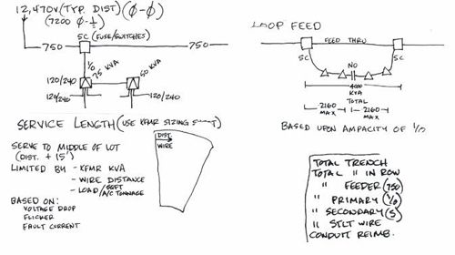
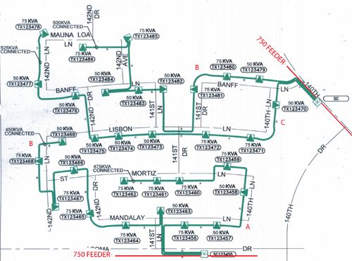
And here is one of their "sample" drawings...except I added the red 750 and phasing to show the typical feeder setup (for clarity). I see a few obvious places (in their example) where a "loop" could be added, except I'm still unclear about how much multiple conductor I can run parallel in the same trench and still not de-rate the conductors too much. I seem to remember seeing a limit somewhere. I'm looking forward to trying to make sure I do it "right" with the linecrew/maintenance in mind.
-
06-01-2013, 05:52 PM #14
Senior Member
- Join Date
- Oct 2008
- Posts
- 146
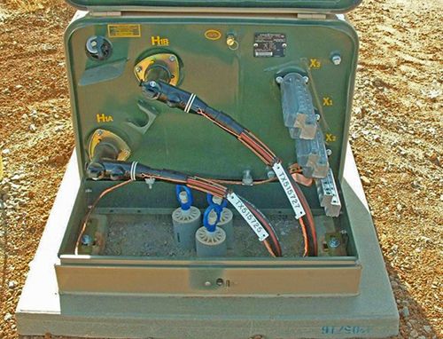
The only issue I have is subpar labeling. In underground, labeling is everything. I've opens boxes before with just a bunch of blank white flags staring back at me. I'm sure they had black marker on them at one point but not anymore
") The yellow number stickers beside the primary bushings are the way to go.
The yellow number stickers beside the primary bushings are the way to go.
-
06-01-2013, 07:52 PM #15
Senior Member
- Join Date
- Oct 2006
- Location
- South East Texas
- Posts
- 3,278
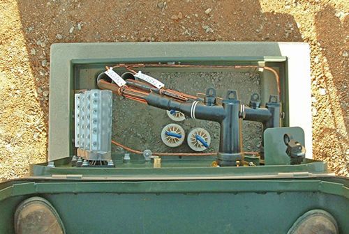
Ummm yeah n the tags needa give a feller the direction that stuff goes from the transformer
sho nuff helps findin the next tub inna fenced in yards subdivision
-
06-01-2013, 09:11 PM #16
Senior Member
- Join Date
- Apr 2004
- Location
- Gainesville FL
- Posts
- 183
The only reason I could possibly see for derating parallel cables is if they are close enough that their combined heat build up causes a problem. Generally, at least on our system, our cables are not loaded to the point where heat becomes a problem. Originally Posted by URDesignerCub
Take only what you earn, give only what you can, learn to respect yourself before you can expect to respect anything or anyone else.
-
06-01-2013, 09:29 PM #17
Senior Member
- Join Date
- Apr 2004
- Location
- Gainesville FL
- Posts
- 183
LNF is correct
I know that at times you are able to tie two circuits together and then switch on a dual circuit transformer loop, however that depends on just how close you are able to tie the two circuits together to where the loop is. The theory of not losing half of a dual circuit loop if you loose a circuit is not enough to make me agree with making dual circuit loops a standard practice. If you have circuit lockout, then you get the majority of power restored thru switching and isolation of the affected areas. Personally I feel that taking the time to switch dual circuit loops during these situations only lengthens the time that the circuit is locked out.
The labelling definately needs to be of a sort that lasts indefinately. I've actually took and drew in the lid of a transformer showing how and where both primary and secondary runs went in relation to buildings and such. I mainly did this in apartment complexes and such where things were not as one would expect.Take only what you earn, give only what you can, learn to respect yourself before you can expect to respect anything or anyone else.
-
06-01-2013, 10:04 PM #18
Member
- Join Date
- May 2013
- Location
- SouthWest USA
- Posts
- 44
We seem to have a pretty good labeling system, and I know some of the newer stuff is going to a punched metal tab-label that won't fade into oblivian even if the color fades you can still read the label numbering.
-
06-01-2013, 10:55 PM #19
Senior Member
- Join Date
- Feb 2007
- Location
- Ontario Canada
- Posts
- 1,284
We try as much as we can to loop our switch gear with 1000 MCM on vista switches then branch off to transformers with 1/0. We also try and loop the 1/0 from gear to gear with an open point in between, sometimes they are on different feeders so before we make a parallel on the 1/0 we make a parallel on the trunk, but again only when we are on different feeders. If we loose a circuit and are just picking up customers there is no parallel so we don't have to make the trunk parallel first. By using Vista switches it allows us to use fewer riser poles and have fewer transformers on 1 loop than if you went pole to pole with just transformers on the loop.
-
06-01-2013, 11:12 PM #20
Member
- Join Date
- May 2013
- Location
- SouthWest USA
- Posts
- 44
Featured SponsorrOur system looks similar. I have some drawings/photos posting (but apparently waiting on moderator approval)...but it's pretty much all 750 feeder from Switch Cabinet to switch cabinet, then the primary (loops and radials) are all 1/0 fed from the cabinets. (All in it's own conduit: Feeder, primary and services). Our labeling is pretty good too, as we seem to be going to the "embossed/stamped" metal number "tabs" so even if the color fades you still can read the raised/punched alpha-numbers, and the metal labels are attached at both ends of every cable run. (images to follow).
http://powerlineman.com/lforum/attac...6&d=1370188653Last edited by URDesignerCub; 06-02-2013 at 12:01 PM.